Virtual Local Area Networks (VLANs) divide a single existing physical network into multiple logical networks. Thereby, each VLAN forms its own broadcast domain. Communication between two different VLANs is only possible through a router that has been connected to both VLANs. VLANs behave as if they had been constructed using switches that are independent of each other.
Contents
- 1 Types of VLANs
- 1.1 Port-based VLANs
- 1.2 Tagged VLANs
- 1.2.1 Structure of an Ethernet Frame
Types of VLANs
In principle, there are two approaches to implementing VLANs:
- as port-based VLANs (untagged)
- as tagged VLANs
Port-based VLANs
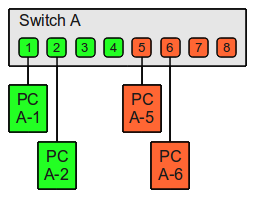
With regard to port-based VLANs, a single physical switch is simply divided into multiple logical switches. The following example divides an eight-port physical switch (Switch A) into two logical switches.
| Switch A | ||
|---|---|---|
| Switch-Port | VLAN ID | Connected device |
| 1 | 1 (green) | PC A-1 |
| 2 | PC A-2 | |
| 3 | (not used) | |
| 4 | (not used) | |
| 5 | 2 (orange) | PC A-5 |
| 6 | PC A-6 | |
| 7 | (not used) | |
| 8 | (not used) | |
Although all of the PCs have been connected to one physical switch, only the following PCs can communicate with each other due to the configuration of the VLAN:
- PC A-1 with PC A-2
- PC A-5 with PC A-6
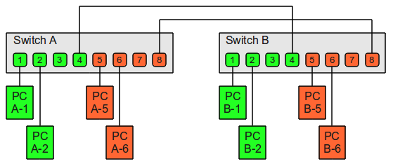
Assume that there are also four PCs in the neighboring room. PC B-1 and PC B-2 should be able to communicate with PC A-1 and PC A-2 in the first room. Likewise, communication between PC B-5 and PC B-6 in Room 2 and PC A-5 and PC A-6 should be possible.
There is another switch in the second room.
| Switch B | ||
|---|---|---|
| Switch-Port | VLAN ID | Connected device |
| 1 | 1 (green) | PC B-1 |
| 2 | PC B-2 | |
| 3 | (not used) | |
| 4 | (not used) | |
| 5 | 2 (orange) | PC B-5 |
| 6 | PC B-6 | |
| 7 | (not used) | |
| 8 | (not used) | |
Two cables will be required for connecting both VLANs.
- One cable from Switch A Port 4 to Switch B Port 4 (for VLAN 1)
- One from Switch A Port 8 to Switch B Port 8 (for VLAN 2)
Note on PVID: For some switches it is necessary to set the PVID (Port VLAN ID) on untagged ports in addition to the VLAN ID of the port. This specifies which VLAN any untagged frames should be assigned to when they are received on this untagged port. The PVID should therefore match the configured VLAN ID of the untagged port.
Tagged VLANs
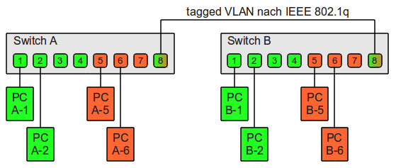
With regard to tagged VLANs, multiple VLANs can be used through a single switch port. Tags containing the respective VLAN identifiers indicating the VLAN to which the frame belongs are attached to the individual Ethernet frames. If both switches understand the operation of tagged VLANs in the example above, the reciprocal connection can be accomplished using one single cable.
Structure of an Ethernet Frame
The VLAN tag is added to an Ethernet Frame by MAC address.


